
Smoother Low-Speed Sailing Through Severely Choppy Water
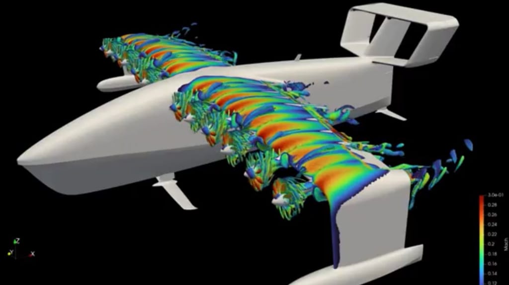
Evolving innovation promises to enhance ride smoothness of ferry vessels that sail through severely choppy water at many locations internationally. Innovations that originate in aeronautical wing design to improve low-speed flight capability are applicable to hydrofoil innovation required to lift vessel hulls above water at low sailing speed. Such innovation would allow larger vessels to sail through shallow waterways, with potential reduction in propulsive power requirements.
Introduction
Ferry vessels provide essential services in many regions internationally, often sailing across bodies of choppy water that are prone to heavy swells and waves. Such sea conditions often result in service cancellations or delayed departures. Hydrofoils installed under ferry vessels to raise the hull above water require high engine power to accelerate vessels to higher speed, to achieve a smooth ride when sailing through choppy water. Hydrofoil configuration often duplicated the cross-sectional profile of aeronautical wings on a much smaller scale, combining a curved upper surface with a flat under surface.
Seawater has 850 times the density of air, allowing the equivalent of a small-scale model aircraft built into the lower level of the keel of hydrofoil surfboards to carry the combined weight of surfer and board. Surfers have commented about smoother sailing through choppy water. Adapting advances in aeronautical wing design that enhance low-speed flight to hydrofoil design promises to enhance ride characteristics of ferry vessels that need to raise hulls above choppy water at low sailing speed. Such advances promise to reduce service cancellations and delayed departures due to adverse sea conditions.
Sailing Above Water
The cross-sectional profile of aeronautical wings and hydrofoils includes a curved upper surface that causes air and/or water to accelerate to higher speed across the upper surface as the wing/hydrofoil moves forward. Further acceleration creates a low-pressure zone that attracts a substantial volume/mass of water/air from higher elevation to flow downward over the curved surface. In accordance with Newton’s Law of Motion that states, “for every action there is an opposite and equal reaction,” the downward flow of mass over the rear section of the upper surface generates upward “lift.”
However, there are proven and tested methods by which to achieve upward “lift” at comparatively low speed on the airplane runway, with potential to achieve the same result while sailing in water. Several such methods have been tested and proven using small aircraft using radio-controlled small-scale working models, as well as in full-size pilot-flown aircraft. There is scope to adapt such proven and tested innovations to hydrofoils, to lift vessel hulls above water at low sailing speed.
U-Shaped Wing/Hydrofoil
During the 1950s, the U-shaped wing developed by Willard Custer placed the engine and propeller inside a U-shaped section of the wings. A fast flow of air passing through the U-shaped section produced a low-pressure zone, which in turn generated lift at very low airplane speed. Adapting the U-shaped wing to maritime operation while submerged in water under a boat hull would place the propeller immediately upstream of a submerged U-shaped section of hydrofoil. A fast stream of water flowing through the inner side of the U-shaped section at greater than sailing speed would produce a low-pressure zone of water.
The low-pressure zone has the potential to generate upward lift, even sufficient to raise the hull of a vessel above water. While U-shaped sections incur structural issues with aircraft wings, U-shaped hydrofoils secured deep under a vessel hull using extended-height struts would avoid the structural issues of aeronautical wings. Mechanically connected propellers that rotate at identical speed and are located upstream of each hydrofoil would push a stream of water through a submerged hollow tube that connects into the entrance of the lower end of each U-shaped hydrofoil. This would assure equal lifting force at each U-shaped hydrofoil.
The Blown Wing/Hydrofoil
Following successful demonstration of U-shaped wings, other innovators used different methods to flow high-speed air streams across the curved upper surface of wings of small-scale aircraft. There is potential to achieve a comparable result with hydrofoils. The installation of a paddle wheel ahead of each wing pushed a fast-moving air stream across the wing’s curved upper surface, achieving upward lift at low flight speed. A row of multiple parallel small propellers pushing air over the entire wing upper curved surface achieved the same result, providing a basis for future hydrofoil operation.
For maritime application, a conventional propeller installed upstream of the hydrofoil may push water into a circular duct that, along its length, would transition at constant cross-sectional area into a wide rectangular duct with its outlet located just ahead of the hydrofoil. A stream of water flowing at elevated speed over the hydrofoil’s curved upper surface would generate upward “lift” at lower sailing speed, with additional potential to lift the hull of a heavier vessel upward at lower sailing speed.
that matters most
Get the latest maritime news delivered to your inbox daily.
Conclusions
In commercial sailing, there is a need to provide smoother ride characteristics involving passenger ferry vessels that sail through severely choppy water, with reduced pitch and roll motions. There is also an economic basis for comparatively large and heavy vessels to be able to sail through shallow sections of navigable water. Wind-powered vessels have sailed directly into headwinds at speeds of up to nine knots, with potential for higher speed courtesy of future innovation. In all cases, vessels would require innovations in hydrofoil development that allow for sailing at low speed with hulls above water, including as low as five knots.
The opinions expressed herein are the author's and not necessarily those of The Maritime Executive.