
Customized Energy Saving Devices Yield Big Fuel Savings
Energy saving devices offer fuel savings of hundreds of thousands of dollars per year to ship owners and operators. CD-adapco talked to IBMV's Steve Leonard, who explains how STAR-CCM+ software allows Becker Marine to guarantee fuel savings across a wide range of vessels
One of the biggest concerns facing ship builders and operators is energy efficiency and fuel savings. To a certain extent, fuel savings can be achieved using modern, efficient hull designs that direct the flow smoothly around the vessel and into the propeller. However, most of the world’s commercial trade shipping is dominated by older vessels that were designed without the benefit of modern tools such as Computational Fluid Dynamics (CFD) and Design Exploration.
In order to obtain a desirable level of fuel economy and reduced emissions, shipowners and operators often choose to fit Energy Saving Devices (ESDs) to their vessels. ESDs are most commonly stationary flow directing devices that are positioned near the propeller, either ahead of the propeller, fixed to the ship’s hull, or behind, fixed either to the rudder or the propeller itself.
Experience has also shown that even the most recent hull designs show significant potential for improving the powering performance by fitting ESDs.
Probably the most successful ESD currently in operation is the Becker Mewis Duct, a novel power-saving device which has been developed initially for full-form slower ships that allows either significant fuel savings at a given speed or alternatively for the vessel to travel faster for a given power level.
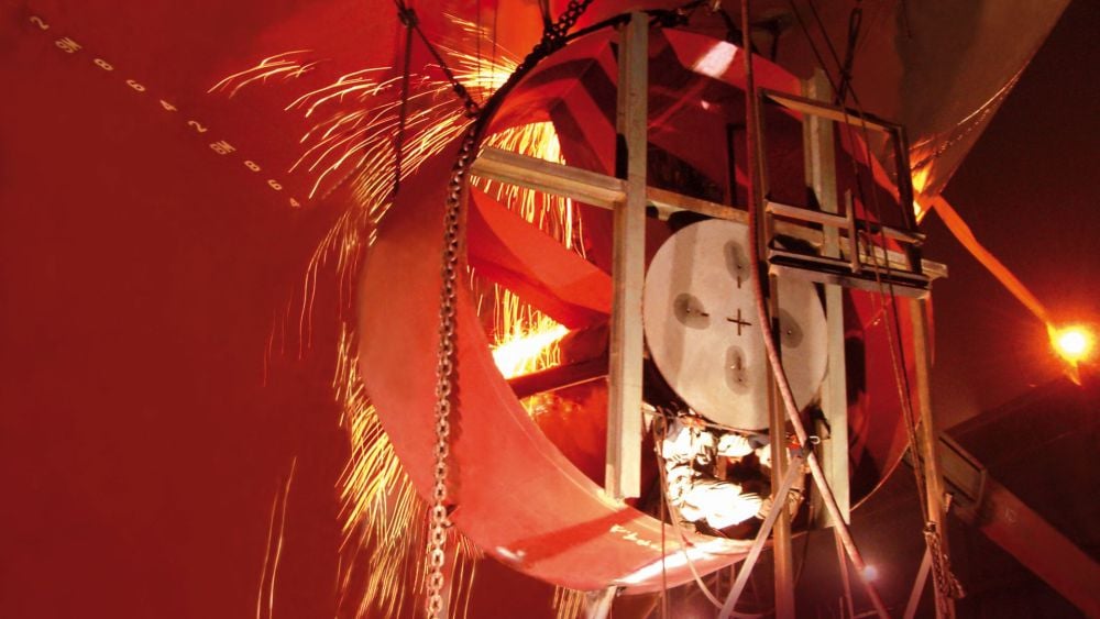 Duct installation
At first glance, the Becker Mewis Duct is a relatively simple piece of equipment, consisting of a duct containing a number of integrated angled fins. The main benefit of the duct is that it produces a net forward thrust, as well as straightening and accelerating the hull’s wake into the propeller. The fin system introduces a pre-swirl to the ship’s wake which reduces losses in the propeller slipstream, resulting in an increase in propeller thrust at a given propulsive power. Both effects contribute to each other. However, in order to function correctly, both the duct section properties and the orientation and design of each of the fins has to be specifically optimized for each new hull form in order to improve the wake flow from the hull.
In simple terms, this can be described as “something for nothing”; the Becker Mewis Duct harnesses energy contained in the frictional boundary layer of the hull and uses it to increase the overall hydrodynamic efficiency of the vessel. The power savings that can be achieved from the Becker Mewis Duct largely depend on the hull block coefficient and propeller’s thrust loading. Typically, power savings are in the range of three percent for multi-purpose ships, up to eight percent for tankers and bulk carriers can be expected. Fuel savings are on average five to six percent, rising up to eight percent in combination with a Becker Rudder. The savings in fuel/power that can be achieved are independent of the draught of the ship and her speed. NOX and CO2 emissions are also reduced.
The Becker Mewis Duct was first introduced to the market in September 2008. The first full-scale installation was completed on the 54,000 dwt multi-purpose carrier Star Istind of the Grieg Shipping Group in September 2009. The estimated power saving for that ship is about six percent.
The AS Valeria, a 57,000 dwt bulk carrier, achieved fuel savings of five percent (predicted by CFD and confirmed in sea trials) resulting in the reduction of 1,000 tons of CO2 per year.
A vessel of 55,000 dwt will use about 160 tonnes of fuel per day at normal cruising speed. Over the course of a year, a five percent improvement in fuel consumption would save over 2,000 tonnes of fuel over the course of a year, resulting in cost savings of around $500,000.
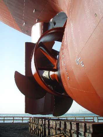 Duct installed on the 1998-built Bow Flora, a 37,000 dwt chemical tanker operated by Odfjell
Such is Becker Marine’s confidence in the duct that they are prepared to offer a full refund on any device that does not deliver pre-agreed fuel savings during model testing. With this sort of guaranteed performance, it is a low-risk investment for most ship owners and operators, as return on investment is typically achieved within a year of installation, and is certainly much cheaper than investing in a new ‘eco-ship’.
This has proved to be an excellent business model for Becker Marine Systems who, since the product was launched in 2008, have now installed over 1,000 of the devices.
Steve Leonard is the Head of Research & Development at IBMV, a wholly owned subsidiary of Becker Marine Systems tasked with developing, engineering and launching innovative technological solutions into the maritime market. Leonard and his team performed the CFD calculations for the first Becker Mewis Duct in 2008, and have subsequently developed a process which employs 13 engineers and naval architects, delivering hundreds of ducts per year.
“The success of the Becker Mewis Duct depends almost entirely on the CFD process that we use to define it,” says Leonard. “Without accurate CFD simulations, we wouldn’t be able to tune each duct to the specific flow conditions generated around each hull. Although there are similarities, the duct that we design for each vessel is absolutely unique and a result of the careful tuning of over 40 design parameters. No two are ever alike.”
Not only does Leonard’s team have to deliver guaranteed energy savings they also have to deliver them within a strict timescale. “From the moment we receive a new order, we have typically six weeks to find the required energy savings,” says Leonard. “This timescale is strictly fixed, by the fact that the towing tank slot is reserved well in advance and cannot be moved. If we can’t improve the energy efficiency of a given vessel within that time, then we’ve basically failed. There are no second chances.”
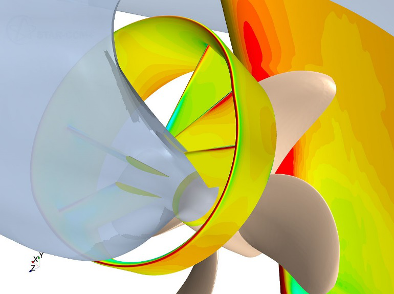 FIGURE 3: Dynamics pressure distribution on the duct and rudder
The maritime industry tends to be conservative, and self-propulsion tests remain the benchmark for proving the powering performance of vessels for most shipbuilding contracts. Few customers are even aware of the intensive CFD effort that goes into designing and tuning their Becker Mewis Duct, concentrating only on the final fuel savings demonstrated during model testing. Any variation between CFD and towing tank predictions is investigated thoroughly using further CFD calculations.
The vast majority of CFD calculations are performed at model scale. To verify that scaling effects do not have a significant influence and also ensure good cavitation performance, the IBMV team runs a series of final full scale calculations.
Although this problem seems well suited for an automated “optimization” process, in which a computer algorithm chooses the next design configuration (rather than an actual human), based on the parametric exploration of previous iterations, the Becker Mewis Duct does not lend itself easily to automated design exploration.
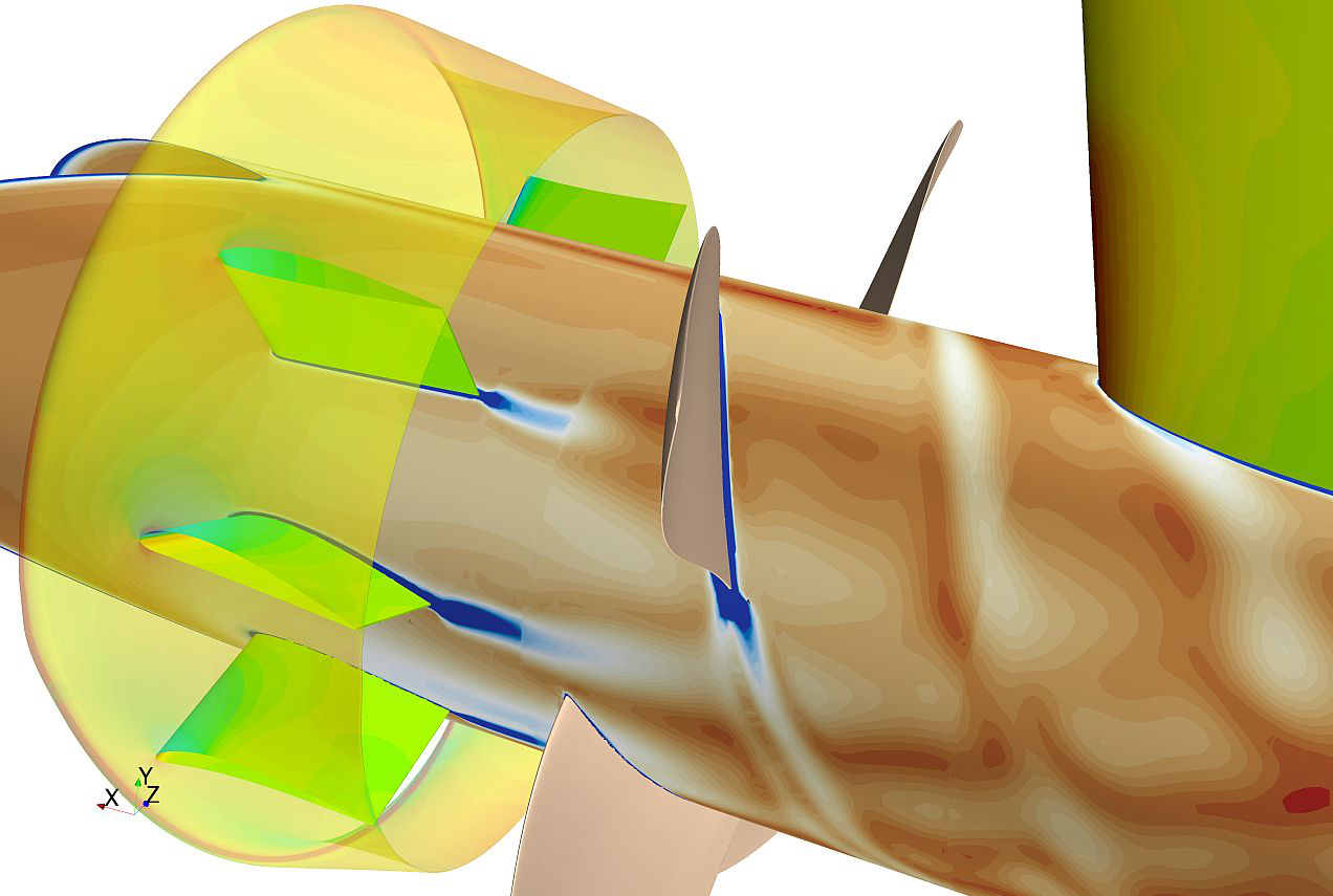 Vorticity magnitude on a cylinder section inside the duct showing the effect of the rotating propeller
The reason for this, Leonard explains, is that it is almost impossible to reduce the flow around the duct to a handful of numerical parameters that could be used to fully define the next design iteration. Instead, Leonard relies on a team of experienced Naval Architects and Hydrodynamicists who are tasked with visually inspecting all data that are automatically generated at the end of each STAR-CCM+ simulation, and identifying adverse flow features through the duct, fins and propellers, and suggesting a corrective action for the next iteration.
In most cases, the team is able to obtain optimal energy savings within about 10 design iterations, although some credit here must also go to the experience of Leonard’s team, who through the experience of fine-tuning many hundreds of these ducts are able to use their engineering judgement to define an initial design that offers a solid foundation for further improvement. The better designed the hull of the vessel is, the less energy is wasted in the wake, and the harder it is for Leonard’s team to obtain big savings.
With some excitement, Leonard fondly recalls the team’s solitary “one and done” duct design, in which it was subsequently shown that the initial design iteration delivered the required energy saving without the need for any further optimization. In reality, this is also a victory for the IBMV process, as the initial design was configured by an engineer who used knowledge from the hundreds of previous duct design studies when choosing the design parameters for this particular duct.

that matters most
Get the latest maritime news delivered to your inbox daily.
The success of IBMV in delivering over 1000 Becker Mewis Ducts offers a clear demonstration of the value of engineering simulation (and in particular CFD) as a tool in the marine design process, informing decisions, and providing a constant stream of data to improve the real-world performance of vessels.
Without intensive design exploration, driven by experienced engineers, it would be impossible for Becker Marine Systems to deliver finely tuned energy saving devices that offer guaranteed performance within a strictly controlled time scale. Not only has this delivered multiple millions of dollars of fuel savings to their customers, but it has also played a significant role in reducing harmful CO2 and NOX for the shipping industry as a whole.
The opinions expressed herein are the author's and not necessarily those of The Maritime Executive.