
Understanding Hazardous Area Classification on Ships and Offshore
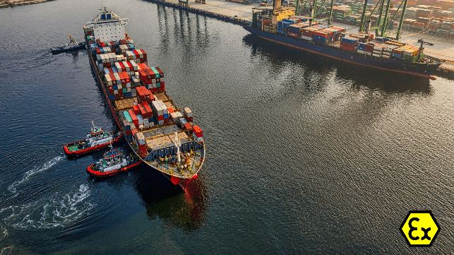
Explosive gas atmospheres are a constant consideration in the design and operation of ships, FPSOs and offshore platforms. From cargo pump rooms to vent masts, every area where flammable vapor might occur must be identified and managed. This process, known as Hazardous Area Classification, forms the basis for safe design under IEC 60092-502, IEC 60079-10-1, and class rules such as those of ABS and Bureau Veritas.
Why Hazardous Area Classification Exists
When hydrocarbons are handled, vapors can mix with air to form explosive atmospheres. Even a small ignition source – a spark, a hot surface, or a malfunctioning mobile phone – can trigger a fire or explosion. The goal of hazardous area classification is to map where such mixtures can appear and to define what level of protection electrical and mechanical equipment must provide.
On ships and offshore installations, the classification does more than mark danger zones. It directly influences how cables are routed, where ventilation inlets are placed, and what type of equipment is installed. Correct classification prevents ignition and allows maintenance to take place safely without shutting down large parts of a plant.
Defining the Zones
The IEC zone system divides hazardous areas by the frequency and duration of an explosive atmosphere:
Zone 0: An explosive gas atmosphere is present continuously or for long periods. Typical examples are the interiors of cargo and slop tanks, pipelines containing flammable liquids, and pressure-relief vent lines. Equipment here must meet Equipment Protection Level (EPL) Ga – the highest protection standard – typically achieved through Ex ia intrinsically safe circuits or Ex ma encapsulation.
Zone 1: An explosive atmosphere is likely to occur in normal operation but not continuously. This includes pump rooms, manifolds, and cofferdams adjacent to cargo tanks that lack mechanical ventilation. IEC 60092-502 and the IMO IGC Code (2016 edition) specify boundaries extending typically 3 meters from vent outlets, loading manifolds, or pump-room openings, though exact distances vary based on ventilation rates and release characteristics. Equipment requires EPL Gb protection: Ex db flameproof, Ex eb increased safety, Ex ib intrinsic safety, Ex mb encapsulation, or pressurized Ex px enclosures.
Zone 2: An explosive atmosphere is not likely in normal operation and, if it occurs, will exist only briefly. Typical examples are areas extending several meters beyond Zone 1 boundaries, around vent masts, or deck areas above cargo tank tops. EPL Gc equipment is permitted: Ex ec, Ex ic, Ex mc, or Ex pzc types. This zone often extends 10 to 15 meters from Zone 1 sources depending on ventilation and layout.
Areas outside these limits are classified as non-hazardous, but adjacent spaces such as machinery rooms still require overpressure ventilation and gas detection systems to prevent vapor ingress.
How the Classification Shapes Ship and Rig Design
Hazardous area classification determines much of the physical layout of an offshore facility. Zone drawings produced during HAZID and HAZOP studies become the blueprint for every downstream decision.
Electrical systems must match zone requirements exactly. Cable entries between zones use certified barrier glands or sealing fittings to prevent gas migration through cable cores. Cable trays and metallic coverings are kept electrically conductive and bonded to the vessel structure to avoid static discharge, as specified in IEC 60092-502 and class society rules.
Ventilation plays a critical role. Machinery spaces, ballast-water-treatment rooms, or battery compartments located near Zone 1 areas must be maintained under positive pressure with continuous monitoring. Automatic alarms trigger if pressure drops below set point, and in critical cases, equipment shuts down to prevent vapor ingress. Air intakes are positioned outside hazardous limits – often 10 meters or more from vent outlets – while exhausts discharge clear of accommodation and control rooms.
Gas detection is mandatory at Zone 1 and 2 boundaries and within enclosed spaces that could accumulate vapor. Fixed hydrocarbon detectors, typically set to alarm at 20% LEL (Lower Explosive Limit), provide early warning. Portable detectors are required for entry into tanks, cofferdams, or any space that has been closed or poorly ventilated.
Common Ignition Sources Offshore
The main ignition hazards offshore include:
- Hot surfaces: Exhaust manifolds, turbocharger casings, or overheated bearings
- Electrical arcing: Switching contacts, motor brushes, or loose connections
- Mechanical friction: Grinding, impact tools, or non-sparking bronze tools used incorrectly
- Static electricity: Rapid fluid flow through pipelines, hoses, or tank cleaning equipment
- Radio frequency emissions: Handheld radios, mobile phones, or improperly bonded antennas
Controlling these sources requires both design and procedure: grounding and bonding of all piping and equipment, temperature monitoring of machinery surfaces, certified explosion-protected apparatus, and strict hot work permit systems. Hot work requires strict permitting: spaces must be certified gas-free, continuously monitored, and attended by fire watch personnel. Work is not permitted in classified zones without prior gas-freeing and reclassification.
Maintenance and Verification
Class societies and flag states require ongoing inspection to confirm that installations continue to meet their original certification. Periodic tests include:
- Insulation resistance of cables and terminations
- Verification of seals on Ex d and Ex e enclosures
- Surface temperature measurement of luminaires and motors
- Ventilation flow rate and pressure differential checks
- Gas detector calibration and functional testing
Records are maintained under the ship's Safety Management System (SMS) and reviewed during audits and port state inspections. Any modification to layout, equipment, or ventilation triggers a Management of Change (MOC) procedure, requiring re-assessment of zone boundaries and updates to hazardous area drawings. As-built documentation must reflect reality – discrepancies between design intent and installed condition are a common finding during audits.
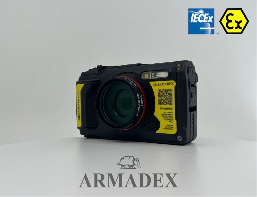
Training ensures that crew and contractors understand where zones begin and end, which tools are permitted, and how to respond if gas is detected. Technicians working in Zone 2 areas often use an intrinsically safe camera and inspection tools to document equipment conditions without breaching safety boundaries. This enables verification of corrosion, cable terminations, and labeling during operation.
Temporary and Dynamic Hazards
Not all hazardous areas are permanent. Tank entry, cargo transfer upset conditions, or maintenance activities can create temporary Zone 0 conditions in normally safe spaces. Gas-freeing procedures, continuous monitoring, and controlled access prevent incidents during these operations. Understanding that zone boundaries can shift with operational state is as important as knowing the static classification.
Conclusion
Hazardous Area Classification is not a theoretical exercise. Rather, it is a detailed engineering map that supports safety across the entire lifecycle of an offshore structure. By applying standards such as IEC 60092-502 (2nd edition, 2024), IEC 60079-10-1, IMO SOLAS, and the IGC/IBC Codes, designers and operators control ignition risk even in the harshest marine environments.
From the welds around a cargo-tank bulkhead to the tools used during inspection, every decision supports one objective: maintaining safe operations in the presence of explosive atmospheres at sea.
This post appears courtesy of Armadex. For more information, visit https://armadex.com/product/atex-camera/.
The opinions expressed herein are the author's and not necessarily those of The Maritime Executive.